你的位置 :

首页

/

污水

/

固液分离

/

滗水器

滗水器

产品描述: 滗水器

SBR FLOATING DECANTER
 
SBR Rotary Floating Decanter
 
Introduction
The rotary decanter is specially designed for large-scale sequencing and batch biological treatment systems. It can realize the laminar flow state of the water entering the outlet weir during the decanting process, and balance the falling speed so that the water output remains unchanged. It is a circulating activated sewage treatment system. Key equipment for mud process.
 
The rotary decanter is an important equipment in the Sequencing Batch Reactor Activated Sludge Process (SBR). It is also the most widely used in domestic. This kind of water decanter can work steadily, easy control, no leakage, flow smoothly and not disturb the sludge. Since the SBR process using a batch reactor, not need secondary sedimentation and sludge return equipment, can save a lot of investment in infrastructure and with good treatment effect, which has been widely promoted in our country. Its basic operation procedure composed by water fill, react, settle, draw and idle five basic process. It's a complete cycle from waste water fill to its idle. The rotary decanter achieves the function to drain the treated water quantitatively and regularly, that makes it possible to continuously treat the water in SBR pool which is the final purpose.
 
Work Process:
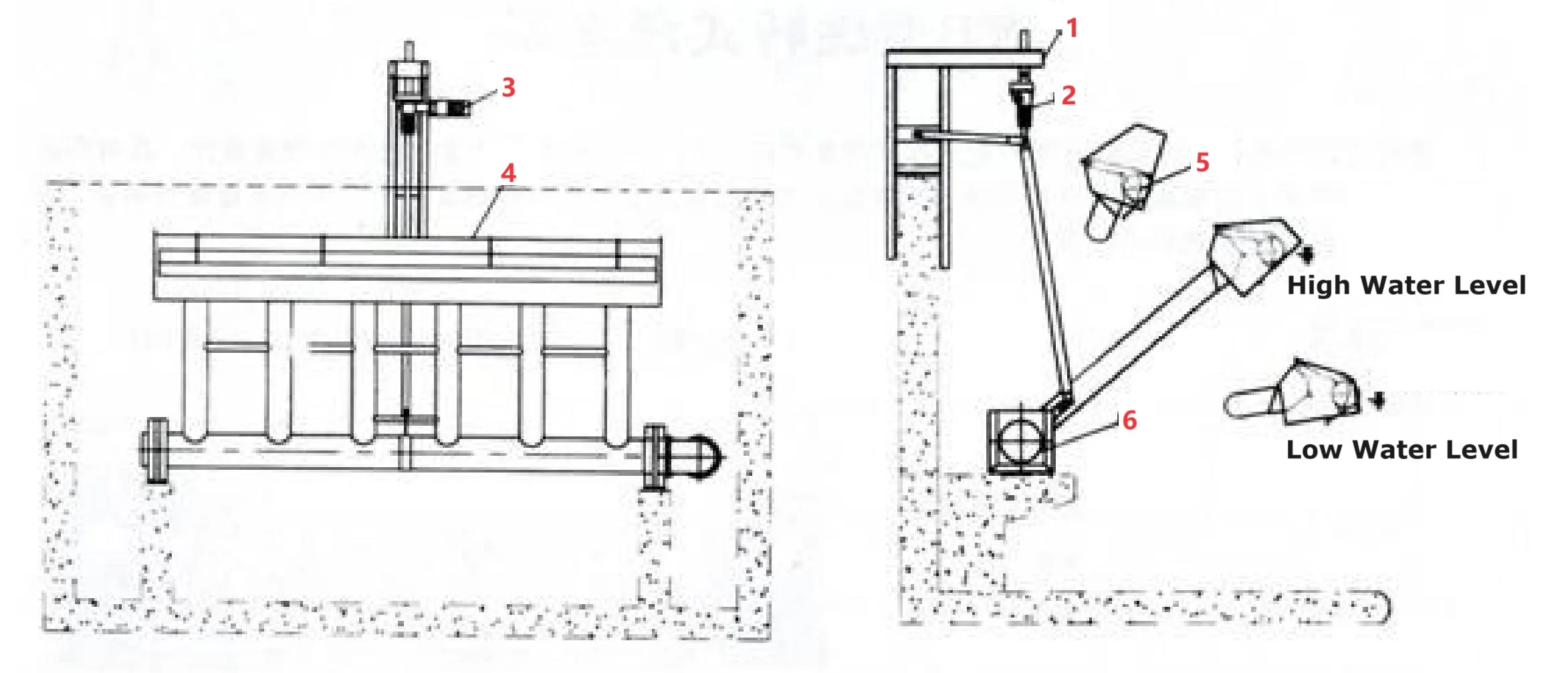
During the aeration and settling phases, the decanter is located above the high liquid level in the main aeration zone. When decanting water, it drops below the water surface for drainage. When the water level drops to the low water level, the decanter returns to the initial position.
 
Features:
The decanter realizes automatic speed change during operation and has a wide adjustment range. The operation of the equipment is synchronized with the water level drop, and the drop speed is uniform speed. The operating speed during decanting can be selected according to different water qualities. It is different from the slide lifting device, but also different from the pneumatic or hydraulic lifting device.
The frequency converter used in the electronic control system is installed in the local control box, which can not only control manually on site, but also accept control signals from the PLC in the central control room to achieve automatic control.
The entire process of water discharge can prevent scum on the water surface from entering the outlet weir.
The underwater rotating parts have good sealing performance, the sealing ring has a long service life and is easy to replace, ensuring the quality of the effluent water.
The decanter is subject to limit control during its operation. to protect the organization from damage.
The driving mechanism is stable and reliable, consumes little power and has low operating costs.
The whole machine has compact structure, easy operation and convenient maintenance.
 
Floating Decanter6
 
Equipment Structure
 
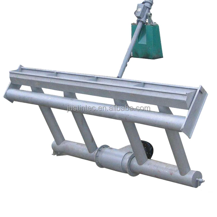
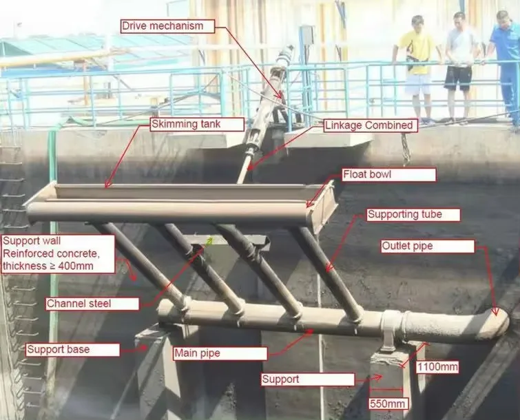
The decanter is composed of a decanting device, a transmission device, a skimmer float device and a slewing bearing. The driving mechanism drives the decanting device and the skimming float device to rotate around the slewing support through the telescopic push rod, thereby moving the decanting weir up and down to achieve the purpose of decanting the supernatant liquid.
 
Screw Type(L)
L-type (screw type) rotary decanter consists of a water collection tank, a float, a drainage pipe set, a slewing support, a screw, a connecting rod device, a guide rail and a transmission device.
 
Electric Push Rod Type(D)
D-type (electric push rod type) rotary decanter is mainly composed of a water collection tank, a float, a drainage pipe set, a slewing support, an electric push rod and an electric control box.
 
Float Type(F)
F-type (float type) rotary decanter is mainly composed of a water collection tank, a float, a drainage pipe group, a solenoid valve, a liquid level gauge and an electric control box.
The electronic control part of the decanter can be controlled by frequency converter and PCL, and can realize manual and automatic control.
 
When draining water, the control element gives a signal and instructs the transmission device to work. The nut rotates and the screw descends at a constant speed, so that the support rod moves in a certain trajectory or is pushed by an electric push rod. The water collection trough moves down at a set speed to complete uniform decanting. water. After the decanting is completed, the liquid level controller gives a signal, the motor reverses, and the water collection trough is moved upward and returns to the preset position.
 
The decanter can follow the water level to continuously and quantitatively drain water. The decanting depth is large, the action is smooth and reliable, and the liquid level is not agitated. The whole machine consumes less energy and has a long service life.


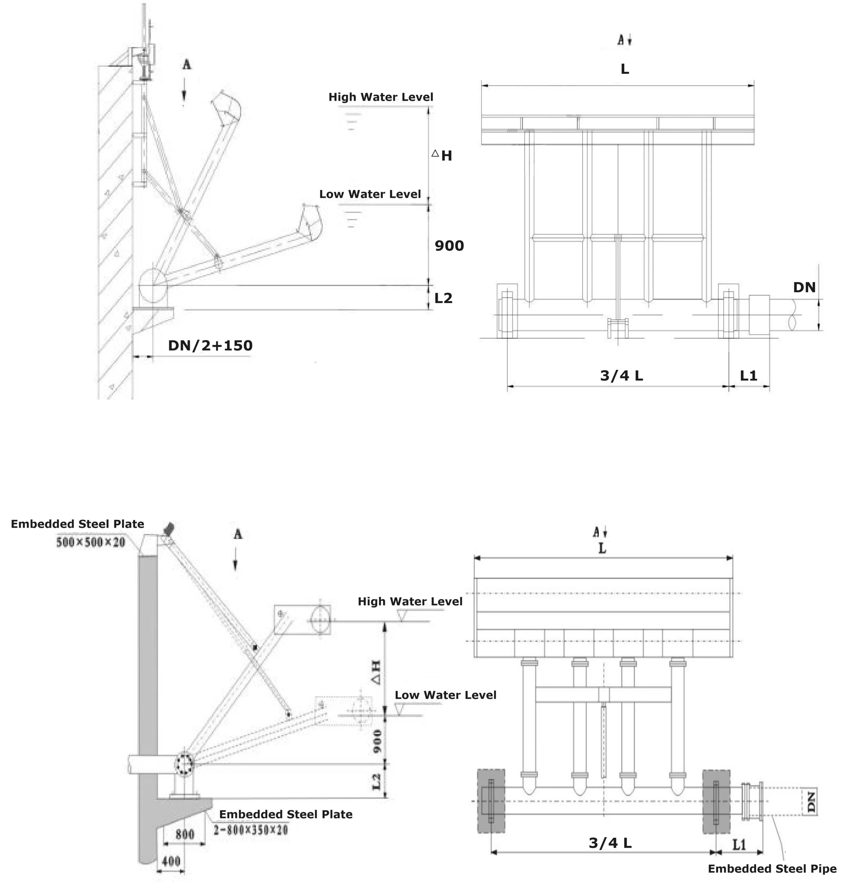
Technical Data Sheet
 

No.

Model

Capacity

m3/h

Effluent Weir length

L(m)

Total Pipe Diameter

DN(mm)

L1(mm)

L2(mm)

∇H(mm)

Power

(kW)

1

RFD-50

50

1.2

150

500

200

≤2500

0.37

2

RFD-100

100

1.5

200

600

250

≤2500

0.37

3

RFD-200

200

3

250

600

250

≤2500

0.55

4

RFD-300

300

4

300

600

250

≤2500

0.55

5

RFD-400

400

5

300

600

250

≤2500

0.75

6

RFD-500

500

6

400

600

300

≤2500

0.75

7

RFD-600

600

7

400

600

300

≤2500

1.1

8

RFD-700

700

9

500

800

350

≤3000

1.1

9

RFD-800

800

10

500

800

350

≤3000

1.1

10

RFD-900

900

11

500

800

400

≤3000

1.1

11

RFD-1000

1000

12

500

800

400

≤3000

1.5

12

RFD-1200

1200

14

600

800

400

≤4000

1.5

13

RFD-1400

1400

16

600

800

500

≤4000

1.5

14

RFD-1600

1600

18

800

800

500

≤4000

1.5

15

RFD-1800

1800

20

1000

800

600

≤4000

2.2

16

RFD-2000

2000

22

1000

800

600

≤4000

2.2


1.Frame      2. Lifting Mechanism          3. Drive Mechanism      4. Outlet Weir        5. Float            6. Underwater Bearing
 
 
Notice:
1. Users need to provide the following parameters when ordering: reaction pool size, water depth, protection height, water level, drainage center height, drainage capacity, and drainage time.
2. The automatic control cabinet or automatic control system must provide the number of decanters, the distance between the reaction pool control room and other requirements.
3. If the user has needs, partial modifications to the equipment can be made through negotiation between both parties without affecting the processing effect.
4. Embedded parts shall be prepared by the demander according to the supplier's requirements. A: Two pieces of pre-embedded iron for the legs, the size is 2-800×400×16 (mm), B: One piece of pre-embedded iron for the electric push rod bracket, the size is 700×300×12 (mm).
 
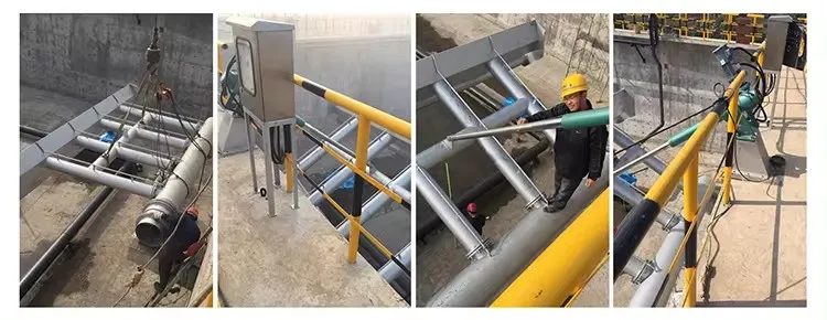
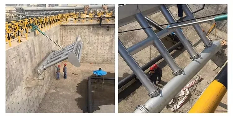
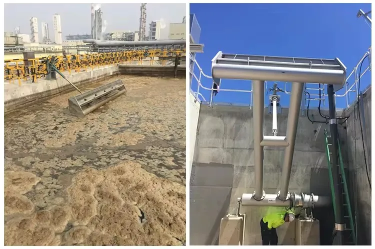
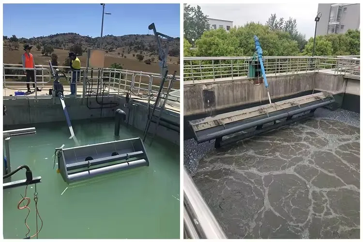
Product Show


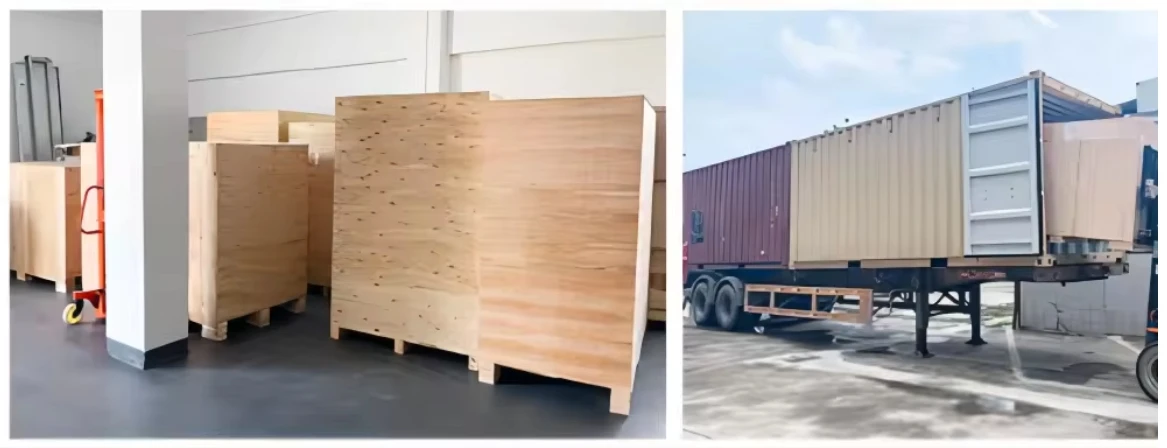
Packaging & Shipping

_20240325180432

在线订购

产品名称:滗水器

热门产品

顶部 客服 联系 扫描 底部
联系我们关闭

公司名称:天津甲乙丁科技有限公司

联系人:Justin

电 话:+86 13312099288

手 机:+86 13312099288

邮 箱:info@justintec.cn

地 址:天津市北辰区北仓镇屈店工业园

用手机扫描二维码关闭
二维码